| Navigation: Templates > Templates by Topic > Graphing >====== Parts of a Graph ====== |    |
This help topic links basic graphing terminology with the template prompts used in the Clarion Graph control.
The Basics
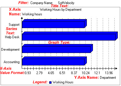
Consider the following graph:
Items marked in red refer to labels not added by the graph control, but are used to define the graph's key elements.
What are we looking at?
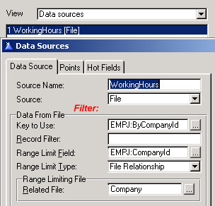
The graph shown above plots a department's working hours devoted to a company. There is a single Data Source defined reading the EmpJob file and filtering the hours read by CompanyId.
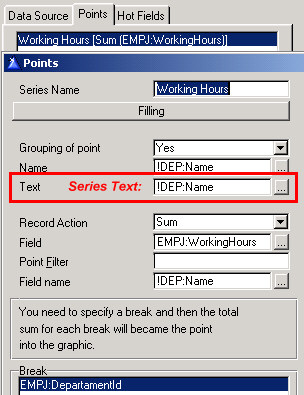
In this graph, there is only one set of data points defined (called a series). This series draws the sum of working hours, and breaks when the DepartmentID (sp) changes:
The other labels are Initial Values, and are initialized as follows:
Title Text See Initial Values > Title > Title Text
Y-Axis Name See Initial Values > Axis > Y-Axis > Name
X-Axis Name See Initial Values > Axis > X-Axis > Name
Graph Type See Initial Values > Graph > GraphType
X-Axis Value Format See Initial Values > Axis > X-Axis > Format of values
NOTE: If blank, this value uses default picture defined in dictionary.
Legend See Initial Values > Legend> Location
Nodes
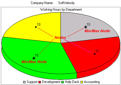
Examine the next graph shown below:
This pie graph is using the same data series points as the column graph above, but there are a few new graph parts that are now visible. The legend is now expanded to identify each piece of the pie chart, and the actual data values of each point in the data series is now displayed in a set of nodes.
The appearance of a node is dependent upon the graph type used. In addition, a node can be used to display additional information about the data point based on a number of template options.
Node information can be displayed in a window control, a tool tip, or on the window status bar.
Nodes are often used as “hot spots” for a drill down graph control. This allows a node value to be passed to the drill down graph control to provide fine control over the elements displayed.
The amount of node information that can be displayed is varied, and controlled by template options in many places.
See:
View: Initial Values > Node
View: Display options > PopUp Menu > Node
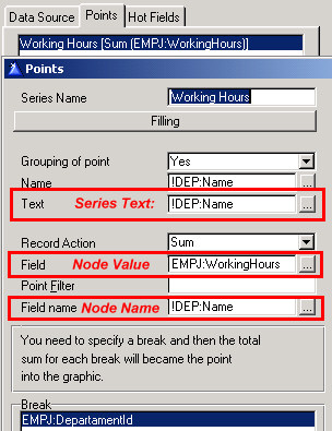
View: Display options > Show > Node Name
View: Display options > Show > Node Value
One last point concerning nodes; you have the option to show a node name or node value. These values are extracted from the Points dialog as shown below:
Advanced Graph Displays
The most important rule to remember when designing a graph display is to keep it simple.
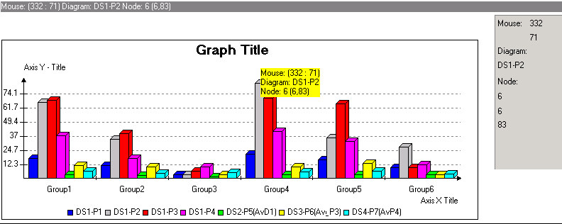
The following graph, captured from the shipping graph example, demonstrates how quickly a graph can become more complex:
This graph shows nearly all of the features available to you using the Graph control template.
The highlight of this graph display demonstrates multiple data points from multiple data sources. In reality, there is only one queue that is processed, but the last three data points rely on a specific average, and could process the queue in a different way. To summarize, one data source is used to process the first four data points (series), and each of the other data sources process an individual average series.
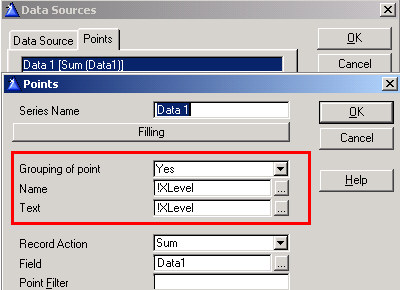
The seven data series are also grouped. This feature is controlled by the following settings:
For each data series, Grouping of point is set to Yes, and the group is based on the value of Xlevel (in our example queue above, XLevel has six values stored ' Group1, Group 2, etc.).
The most effective graph only displays information that is necessary to represent the data; too much detail can make the graph harder to understand.

